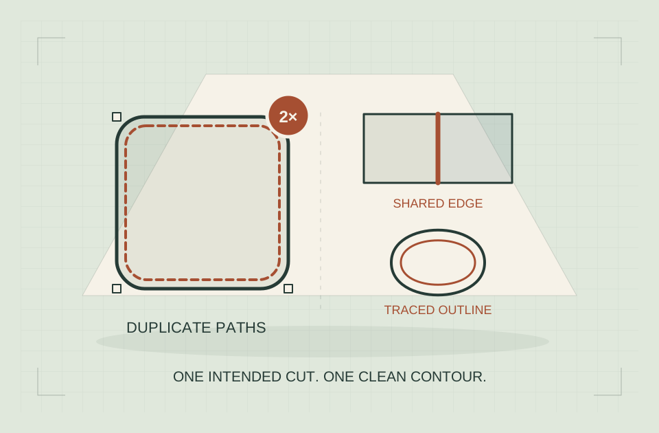
If LightBurn appears to be cutting twice, duplicate cut lines are only one possible explanation. The file may contain identical objects, two shapes sharing an edge, two separate boundaries from a trace, or an intentional repeat in the layer settings.
If LightBurn appears to be cutting twice, duplicate cut lines are only one possible explanation. The file may contain identical objects, two shapes sharing an edge, two separate boundaries from a trace, or an intentional repeat in the layer settings.
Use this order: inspect the planned pass count, remove truly identical objects, then address partly shared segments. Save a copy first. The three categories need different tools, and a trace with two visible boundaries may be correct geometry rather than a duplicate.
Passes → objects → segments
Preview the repeat, inspect layer passes, then choose geometry cleanup or output optimization.
- Whole contour repeats: inspect passes
- Same object twice: Delete Duplicates
- Shared edge repeats: overlap optimization
A five-minute document diagnostic
- Open Window → Cuts / Layers if the layer list is hidden. Identify the layer used by the repeated contour.
- Double-click that layer to open the Cut Settings Editor. Inspect its pass count and any sublayers. Two configured passes explain two planned passes even when there is only one outline.
- Open Preview from the top toolbar. Advance through the suspected contour and distinguish output from traversal moves. This is a software inspection; no material run is needed.
- If one operation retraces the same object, inspect exact copies using Edit → Delete Duplicates on a saved, ungrouped diagnostic copy.
- If only a shared edge repeats, open Optimization Settings in the Laser window and inspect Remove Overlapping Lines. Confirm that optimization is enabled before judging its effect.
- Return to Preview after each change. The expected result is the intended contour or shared edge appearing once per required pass, with all required boundaries retained.
These routes follow the LightBurn 2.1 optimization reference and the Delete Duplicates reference. Controls vary by controller and release; a missing option calls for matching the documentation to your installed version, not changing controller families.
Start with the output, not the thickness of a line on screen
Two paths directly on top of each other can look like one path in the workspace. Conversely, two visibly separate lines may be intentional boundaries of a shape.
Open Preview and observe the sequence around the suspected area. Use its playback or position controls to follow what is being sent. LightBurn’s Preview documentation distinguishes output from traversal moves, which can be displayed in red.
A return movement alone does not mean a second laser-on pass. Confirm whether the planned output retraces the same contour or merely travels back across the workspace.
Write down the symptom precisely. Does the entire outside contour repeat? Does only the edge between adjacent parts repeat? Does the second path run a small distance beside the first? Those observations send the investigation in different directions.
If Preview shows the intended sequence but a physical job behaves differently, preserve the file and move to controller- and machine-specific support. Do not use a document-cleanup tool to conceal an unexplained physical-output problem.
Match the symptom to the first useful check
| Symptom | Likely cause | Action and expected result |
|---|---|---|
| Entire contour repeats exactly twice | Pass count or additional sublayer | Inspect the layer operations; Preview should match the intentionally selected count |
| Pasted shape repeats at the identical location | Whole duplicate object | Ungroup a copy, run Delete Duplicates, then confirm the unwanted copy is gone |
| Middle edge of adjacent shapes repeats | Overlapping segments | Enable the documented overlap optimization and confirm one output along that shared edge |
| Two nearby paths follow a thick scanned stroke | Traced inside and outside boundaries | Decide between filled area, boundary paths and centerline artwork |
| Fill unexpectedly disappears | Duplicate geometry or fill interaction | Inspect exact copies and retain all intentional internal boundaries |
| Preview is right but the physical mark repeats | A problem beyond planned geometry | Preserve the file and investigate the actual machine/controller output |
The table narrows the investigation. It does not establish a fault from appearance alone.
Use a working copy with a clear revision name. If you make a destructive edit, you should be able to compare the result with an untouched source rather than relying only on Undo.
Check deliberate repetition before editing geometry
A perfectly clean outline can run more than once when the layer is configured that way.
Open the relevant layer’s Cut Settings Editor and inspect the settings available for your machine type. Look for pass count and any sublayers applying additional operations to the same geometry. LightBurn’s Cut Settings Editor reference separates these controls and their mode-specific options.
Identify the purpose of each operation. A filled engraving followed by an outline, or multiple supported cutting passes, may be intentional. Keep the operations required by the actual design.
For a document-only diagnostic copy, simplify the selected operation enough to identify what it contributes in Preview. Keep a record of the original values. A temporary diagnostic state is not a replacement production recipe.
If the whole contour repeats twice, checking these settings is more informative than immediately searching for stray nodes. If only a small segment repeats, continue into the geometry checks.
Check what is enabled for output
A design can contain several layers whose graphics occupy similar positions. Inspect which layers actually contribute to the job.
Color is an organizational aid, not proof of a unique physical operation. Two differently colored contours can still describe the same location, while one layer can contain several unrelated objects.
Use a small diagnostic copy to isolate the suspect contour. Keep the neighboring geometry that reproduces the problem, but remove unrelated artwork from that comparison. This makes the sequence easier to follow and the eventual support file easier to understand.
Exact duplicate objects: when Delete Duplicates fits
LightBurn’s Delete Duplicates reference says the tool finds objects that are ungrouped and identical in size, shape, and position. The command is available through Edit → Delete Duplicates; check the matching documentation for your release.
Imagine a 40-mm square copied directly onto itself. The two objects have the same outline and location. That is the kind of redundancy this tool is designed to identify.
Save the original assembly before ungrouping the diagnostic copy. Delete Duplicates searches eligible objects across the document, so inspect more than the current selection after running it.
Afterward, inspect the full design as well as the suspect area. Confirm that the intended geometry remains, then return to Preview to check whether the unnecessary repeat has disappeared.
A cleanup message or an apparently thinner line is not the final acceptance criterion. The planned output and the intended design both need to remain correct.
Run Delete Duplicates on a controlled copy
Save the project as a diagnostic revision. Select the assembly you need to inspect, and use Arrange → Ungroup as required by its grouping. Nested groups can need more than one ungrouping step. Keep the untouched original available because the command searches the document rather than just the selection.
Open Edit → Delete Duplicates; the documented shortcut is Alt+D on Windows or Option+D on macOS. A removed duplicate should leave the intended outline visible in the same location. Recheck Preview, then inspect other filled objects: duplicate removal can change fill behavior as well as repeated line output.
If nothing is removed, use the three questions in the next section. Repeating the command cannot turn different shapes into identical objects.
Why Delete Duplicates may find nothing
A negative result does not prove that the output contains no redundant segments. The objects might be grouped, slightly different, offset, or only partly overlapping.
For example, one rectangle may share its right edge with the left edge of another rectangle. The rectangles are different objects, so there is no reason to delete either entire rectangle merely because the boundary overlaps.
Another file may contain one long segment and two shorter segments lying along it. They are not necessarily identical objects even though some output occupies the same place.
This distinction explains many “remove duplicate lines in project” problems. The issue is redundancy in part of the path, not a complete second copy of an object.
Shared edges: inspect Remove Overlapping Lines
LightBurn’s Optimization Settings reference describes Remove Overlapping Lines as a Cut Planner option for avoiding repeated output where graphics overlap. Its effect depends on the relevant optimization being enabled.
This is a different approach from deleting a duplicate source object. You are asking the output planner to account for overlapping segments rather than deciding that a whole drawing object is unnecessary.
Check the option in the documentation for your release, make one recorded adjustment, and inspect the resulting Preview. Do not change several optimization controls at once if your goal is to understand this one effect.
A two-rectangle example
Suppose two 30-by-20-mm rectangles touch along a 20-mm side. Their combined source outlines have a total length of 200 mm: each rectangle has a 100-mm perimeter.
If the intended output uses the shared side once, the unique combined line length is 180 mm. These are geometric calculations, not LightBurn timing measurements.
The example demonstrates why whole-object deletion is inappropriate. Removing either rectangle would remove three other sides you still need.
It also demonstrates why the intended manufacturing layout matters. Shared-edge cutting must suit your actual parts, material, and process. A digital layout that minimizes line length does not automatically produce acceptable dimensions or retain pieces safely.
If your design requires a gap between parts, keep that gap. Do not move separate parts together merely to make a double-cut symptom disappear.
Use overlap distance carefully
The Material Utilization reference explains that the distance control influences how close lines must be for the planner to recognize an overlap.
That value is not a general-purpose repair tolerance for all geometry. A wide setting can create a misleading preview if you are treating intentional nearby contours as redundant.
Consider two parallel boundaries 0.5 mm apart in a hypothetical decorative shape. Their closeness does not prove they should become one line. They may define a narrow feature the designer intended.
Begin with evidence from the file. Are the segments actually on top of each other? Are they slightly offset because of an export problem? Or are they the two edges of a real feature?
If an export introduced a small offset, correcting the source can be more transparent than concealing the discrepancy with a broad planner tolerance. Preserve the original and compare the corrected geometry before accepting a workaround.
Make the repaired file the next usable revision
Separate editable artwork from exported geometry and a configured machine project.
A traced thick stroke normally has two boundaries
A scanned or raster line has visible area. A standard outline trace can follow both sides of that area, creating a closed shape rather than a single path through its center.
If you then assign that shape to a line operation, the output can follow both boundaries. To the reader who expected a single pen stroke, the laser appears to be cutting twice. Geometrically, however, the two paths are distinct.
LightBurn’s Trace Image documentation explains the image-to-vector workflow. Inspect the trace at the final design size instead of assuming every traced line should be reduced to one contour.
For a logo silhouette, both edges may be correct. For a handwriting-style score line, you may want a center path. The intended output determines which representation is suitable.
LightBurn’s 2.2 feature notes introduce Center Line Trace and identify that release as Early Access at the time of research. Use the feature only when your installed release includes it. Older installations need another suitable centerline workflow.
If your installed release lacks a suitable tool, consider redrawing a small original line design as paths or preparing the intended centerline in an appropriate editor. Verify the result rather than deleting one boundary at random.
Choose the operation that matches the artwork
An outline and a filled area are different instructions.
LightBurn’s Line Mode reference describes following vector contours. Its Fill Mode reference describes scanning inside closed vector boundaries.
If your goal is a solid engraved letter, two contour paths may be the correct geometry for the letter’s outside and inside. The question is how that geometry should be processed, not whether every visible edge should be deleted.
Conversely, changing a cutting outline to Fill to hide an unwanted double contour would change the job. A visual improvement in the workspace is not enough if the operation no longer makes the intended part.
Check a small representative section. State the intended result in plain language: “one scored centerline,” “one outside cut,” or “a filled letter with an open counter.” Then compare the chosen layer mode and Preview with that statement.
Do not adjust power or speed as a way to compensate for the wrong geometric representation. Establish the intended path or area first.
Imported SVG and DXF files need source inspection
If the repeat appears only after import, retain the exported file and compare it with the editable source.
A single visible outline in the authoring application can hide overlapping entities. A CAD export can include geometry from more than one face or sketch. A design can also be imported twice accidentally.
Reopen the exported geometry and inspect its entities. A different extension or another conversion can preserve the same redundant paths.
LightBurn’s File Management reference distinguishes importing graphics from opening native projects. Record the exact path by which the artwork entered the document.
For a vendor-supplied design, send the smallest file that demonstrates the repeat and explain the intended output. Ask for clarification before removing contours whose purpose is unclear.
If a seller provides both SVG and DXF, compare a known feature in each. A difference between formats is useful evidence, but neither format is automatically correct merely because it produces fewer moves.
Reproduce the three cases without firing the laser
Start an empty diagnostic document. Keep the examples separate so the expected output is easy to follow. These exercises follow the documented tool definitions; they are not a claim that we performed an equipment test.
Case A: an identical duplicate. Draw a rectangle, enter a width of 40 mm and height of 20 mm, and duplicate it in place with Edit → Duplicate. Both outlines occupy the same position. Save this state, ungroup if necessary, and run Delete Duplicates. The desired document contains one remaining rectangle. Its geometry should still measure 40 by 20 mm, and its one-pass line output should run around that outline once.
Case B: a partly shared path. In another document, draw two 30 × 20 mm rectangles. Use numeric positions or snapping to make one vertical edge coincide exactly; keep the rectangles as separate objects. Set the intended line operation to a single diagnostic pass and open Preview. Compare the planned shared edge with overlap optimization disabled and enabled. Delete Duplicates is not expected to delete one of the whole rectangles, because they occupy different positions.
Case C: configured repetition. Draw a single rectangle in a third document. In the layer’s Cut Settings Editor, compare a pass count of one with a pass count of two using Preview only. The source geometry is unchanged. Delete Duplicates has nothing useful to remove; the planned repeat follows the operation setting.
For each exercise, write down the expected outline, the setting changed, and what Preview shows. If your result differs, keep the minimal native project and installed version for software support. A small file is easier to interpret than a complex production layout with unrelated shapes.
Verify the entire repaired design
A local correction can have consequences elsewhere. After resolving the suspect area, inspect the complete output rather than assuming the rest of the file is unaffected.
Confirm that intended holes and internal boundaries remain. Check that removing an object has not changed a filled region. Review the order in which the job processes internal and external features within your supported workflow.
Keep the accepted project under a new revision name. Record whether you edited source geometry, changed planner settings, or corrected an accidental repetition in layer settings. Those are different corrections, and the next person opening the project should know which one matters.
A reduction in estimated time is supporting evidence at most. It does not prove the remaining paths are correct, nor does it verify a finished part. The geometry and planned operations are the primary document checks.
Before any physical run, return from the diagnostic copy to a reviewed production configuration and complete the normal workshop readiness checks.
Send support a file that explains the problem
If the repeat remains unexplained, prepare a minimal native project containing the necessary layers and settings, together with the original imported artwork when relevant.
Include your LightBurn version, machine/controller type, expected pass sequence, and the exact area that repeats in Preview. Explain which changes you tried and whether each affected the result.
Screenshots help show the symptom, but they may not expose grouped geometry or duplicate entities. Remove confidential customer content when preparing a shareable example.
For designers selling reusable files, this investigation is also part of validating a deliverable. Our digital products guide discusses keeping editable originals, documented formats, and clear file packages.
The useful fix is the smallest justified change: remove a true duplicate, avoid a redundant overlapping output, or choose geometry that matches the desired mark. Preserve intentional boundaries and supported multiple passes. Once you can explain why each remaining operation exists, you have a much stronger basis for returning the design to production.
Final check before using the repaired project
- The required contours remain, including holes and internal boundaries.
- The layer pass count and sublayers match the intended process.
- Exact duplicate objects are removed only where they were redundant.
- Shared-edge optimization is enabled and its distance setting is deliberate.
- Preview shows the expected number of operations on the formerly repeated area.
- The accepted file has a new revision name and the original remains recoverable.
Keep the working correction with the project: object cleanup, planner optimization, and pass-count changes solve different problems. That short note makes a future imported revision much easier to review.
Affiliate link · We may earn a commission on eligible purchases. How funding is disclosed.
Review the physical setup before running the file
After repairing the geometry, review the physical installation. The accessory catalog can help you research workshop equipment; it is not a remedy for duplicate vectors.
Sources & specifications
Reviewed 2026-10-17. Compatibility tables apply to the manufacturer's equipment; confirm your exact machine, stock and accessories before use.
docs.lightburnsoftware.com OptimizationSettings ↗
Checked · Technical reference checked during the October 17 article revision; no personal equipment testing claimed.docs.lightburnsoftware.com DeleteDuplicates ↗
Checked · Technical reference checked during the October 17 article revision; no personal equipment testing claimed.docs.lightburnsoftware.com Preview ↗
Checked · Technical reference checked during the October 17 article revision; no personal equipment testing claimed.docs.lightburnsoftware.com CutSettingsEditor ↗
Checked · Technical reference checked during the October 17 article revision; no personal equipment testing claimed.docs.lightburnsoftware.com DeleteDuplicates ↗
Checked · Technical reference checked during the October 17 article revision; no personal equipment testing claimed.docs.lightburnsoftware.com MaterialUtilization ↗
Checked · Technical reference checked during the October 17 article revision; no personal equipment testing claimed.docs.lightburnsoftware.com TraceImage ↗
Checked · Technical reference checked during the October 17 article revision; no personal equipment testing claimed.docs.lightburnsoftware.com NewFeatures ↗
Checked · Technical reference checked during the October 17 article revision; no personal equipment testing claimed.docs.lightburnsoftware.com LineMode ↗
Checked · Technical reference checked during the October 17 article revision; no personal equipment testing claimed.docs.lightburnsoftware.com FillMode ↗
Checked · Technical reference checked during the October 17 article revision; no personal equipment testing claimed.LightBurn File Management — version 2.1 ↗
Checked · SVG/DXF imports; text font availability or conversion to paths; native project Import versus Open settings behavior. Not approval of operating settings.Independent research. This article contains an affiliate recommendation; we may earn a commission on eligible purchases. How funding is disclosed.